Robots
Pirate Stage
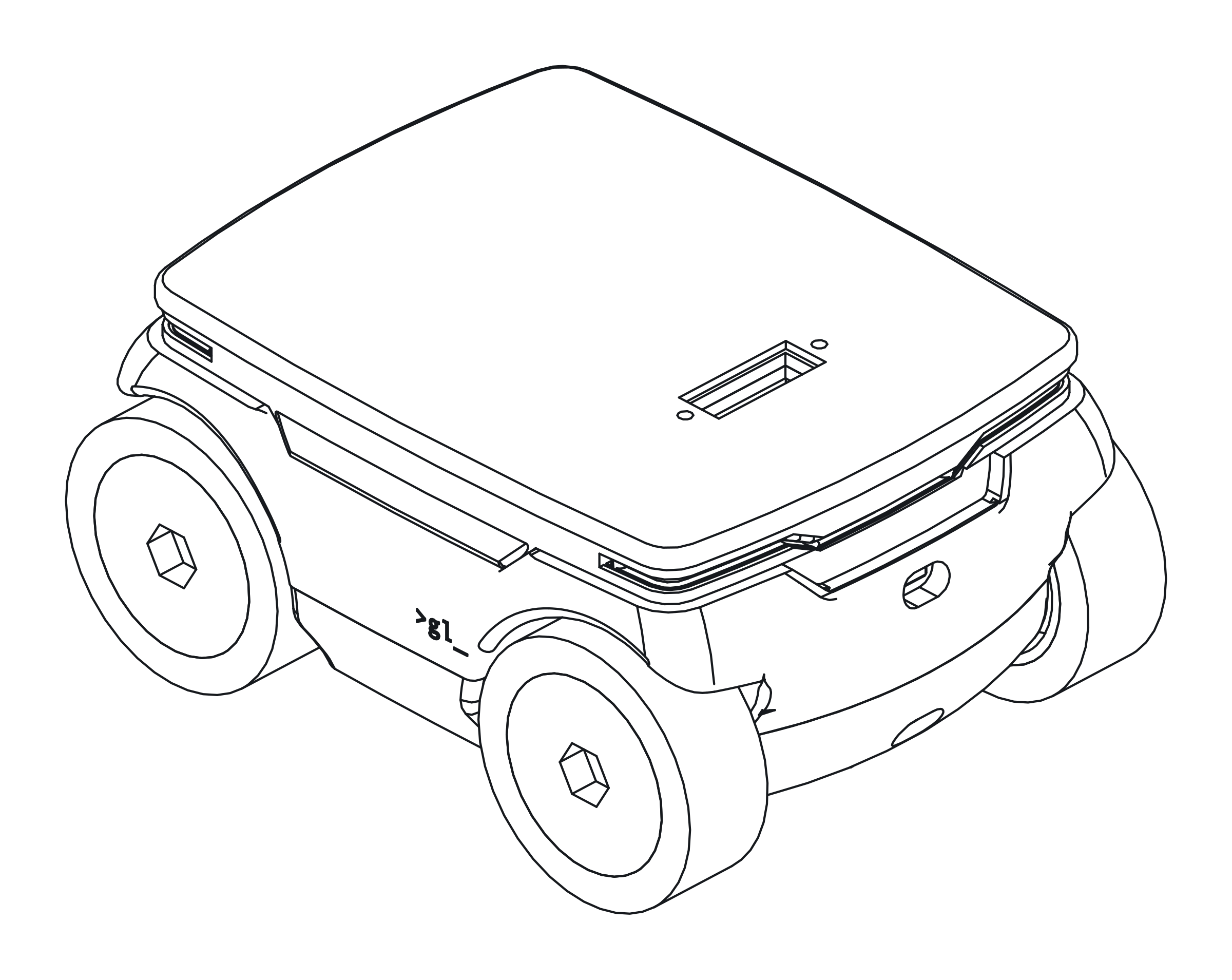
Status. The firmware is written and tested in CI. The car isn’t built yet.
The second robot, a bigger desk car than gl_zero.
| Controller | ESP32 |
| Drive | four gearmotors with encoders |
| Senses | an IMU, and a cliff sensor at each end on an I2C mux |
| Lights | a PWM board |
| Power | a 2S pack |
| Talks | protocol v0, as gl_zero’s firmware does. The same station and page drive it |
| Updates | over the air |
Where its hardware comes from
Its hardware is designed in a separate repo, which isn’t public, and its pin map lives there. It’s being proven on the bench with the bench programs, one for each board, from the PWM board and the IMU to the encoders. They take their pin numbers from the pin map, through a generated header, and so does its fleet firmware.
What its firmware must do
Its firmware follows these rules, from the car’s pin map and a review of its electronics. The bench programs test the hardware behind them.
The firmware so far
It was begun for milestone 1, the car alone, in the roadmap. The code is
firmware/src/pirate-stage, built with pio run -e pirate-stage.
It has the boot order, the motors under their cap and the stall cutoff, the encoders, the battery and the IMU’s
heading, all below. It speaks protocol v0 as gl_zero’s firmware does, with the same rules
(firmware/lib/agent), so the station and its page drive it the same way.
It names itself from its MAC. It takes its Wi-Fi’s name and broker from include/bot_config.h, and its Wi-Fi password and its certificate for
the cluster’s broker over USB, both as in flashing a bot. Updates go over the air with its own
password (Logins and certificates):
scripts/bot-ota upload bot-xxxxxx <its address> pirate-stage-ota.
Its hello says pirate-stage, with encoders and imu. Its telemetry carries the battery’s voltage as batt_v, its
state as battery (ok, low or empty), its heading as heading, and its wheels’ travel (below). The page shows
them all.
A stalled motor sends stall_stop, with the motor. A low or empty battery sends battery_low or battery_empty
(rule 10). The cliff sensors are the reflex at both ends (rule 9, below), and its hello lists tof and tof-rear
for the ones that started. The payload connector comes next.
The stall cutoff and the dead-man run in the main loop, so a loop that hangs would leave the motors running. A watchdog restarts the ESP32 if the loop doesn’t come round for 15 s, longer than a working loop ever holds. The restart lets go of its pins, R22 pulls EEP low, and both drivers sleep. Over-the-air updates switch it off while they run.
The cap, the stall cutoff, the battery’s thresholds, the heading and how a cliff sensor’s frame is judged are in
firmware/lib/chassis. They’re tested on any machine with pio test -e native. None of it has run on the car yet.
For a simulated one, run scripts/sim up 1 --type pirate-stage. It takes its size and track from the CAD and its top
speed from the duty cap. Its encoders and gyro are as imperfect as the simulator’s errors make them
(the simulator’s desk), and it has no cliff sensors yet.
The encoders’ travel goes in telemetry as odo_l_m and odo_r_m, how far each side’s wheels have turned in metres.
Each is the mean of that side’s front and rear encoder, and the page shows it. It waits for the counts per wheel turn
to be measured. Turn a wheel once by hand in ps-enc, then set COUNTS_PER_TURN in lib/chassis/chassis.h. Until
then it’s 0, and the firmware leaves the travel out rather than guess. Milestone 1 checks it against a measured metre.
With the travel and the heading, the car also does its own dead reckoning, every 20 ms as it reads its gyro
(chassis::DeadReckon), and sends where that puts it as odo_x_m and odo_y_m: metres in its heading’s frame, from
where the heading started. The station keeps it as the bot’s own estimate, beside the one it works out itself
(the station). It waits for the same counts per wheel turn.
Telemetry’s l and r are the power after the battery stop and the stall cutoff, but before the ramp, as the
simulator reports them. A side whose motors have both stalled reads 0.
Some things the rules below leave open. These are my choices until the bench says otherwise.
- A stalled motor stays off until its side is asked for nothing, or for the other way.
- The rear cliff sensor holds back reversing, as the front one holds back driving forward (rule 9 at both ends). The car can still turn on the spot, or drive away from what it sees.
- A cliff sensor that didn’t start at boot keeps the car from driving until it restarts. “No driving until both are ranging” has no exception for a broken one.
- A battery reading below 5 V isn’t a pack. It’s the car on USB, or the divider open. The cap stays a full pack’s, and the battery’s state doesn’t change.
- Low and empty need a second under the threshold, so a motor start’s dip doesn’t count. Low holds until the car restarts. Empty is kept in flash until the pack reads 7.4 V for a second (“Low battery” below).
- It doesn’t wait for Wi-Fi at boot. The battery and the encoders run without it, and the motors stay off until the station drives.
- Identify is the wiggle alone. The onboard LED is on GPIO 2, the payload connector’s TX, so the firmware leaves it alone. During an e-stop, when the wheels mustn’t move, identify shows nothing.
- The IMU’s up axis comes from gravity, and its offset from a still second, as in the IMU below.
- No driving over USB. The first version’s serial
driveandstopare gone. On the bench, drive it through a broker on the laptop, the way a real bot on the bench does with a gl_zero.
Each encoder’s direction, which way counts up for forward, isn’t measured yet. Drive forward in ps-enc, then set
each motor’s encSign in main.cpp.
Boot order
- EEP held low. Both drivers’ EEP (GPIO 33) stays low until every motor PWM pin is set up and low. Then it goes high. R22, 10 kΩ from EEP to GND on the board, holds the drivers asleep while the ESP32 boots, before the firmware can drive the pin. That matters because GPIO 14 (front right IN4) puts out PWM during boot. The drivers’ J1 jumpers stay open.
- The PCA9685 (0x40) before the mux (0x70). Clear its All Call (MODE1’s ALLCALL bit) before the first write to the mux. 0x70 is also the PCA9685’s default All Call address, so a write to the mux would reach it too. That’s from the datasheet, not checked yet. Keep MODE2’s OUTDRV set (totem-pole), then wake it.
- The cliff sensors’ firmware, once. Each VL53L5CX takes its firmware, about 86 kB over I2C, at every power-up.
Select its mux channel first, with one write of
1 << channelto 0x70. The IMU is on the main bus and needs no channel.
Motors
The N20s are 6 V, 105 RPM gearmotors on a 2S pack, 6 to 8.4 V. The firmware caps each motor’s PWM duty at 6.0 / VBAT, with VBAT from the battery divider. That’s about 81 % at 7.4 V and 71 % on a full pack. Uncapped, they’d run up to 40 % over their rating, hotter and harder on their brushes. Capped, top speed is about 105 RPM, about 0.33 m/s on the 60 mm wheels.
Stall cutoff. A motor driven above about 30 % PWM whose encoder shows no movement for about 300 ms gets switched
off, and the car sends stall_stop naming the motor (FL, FR, RL or RR). A stalled N20 turns a few watts into heat, an
estimate until it’s measured, and the gearboxes sit in PLA. Both thresholds are starting points, to tune on the bench.
Encoders
- PCNT, x4 quadrature. Each encoder is counted by one of the ESP32’s hardware pulse counters, every edge of both channels. At full speed that’s too many edges for interrupts.
- The glitch filter on. Reading the battery on ADC1 (GPIO 32) is said to pull GPIO 36 and 39, the rear encoders’
A channels, low for a moment. It’s an ESP32 erratum, not checked yet. Each counter’s filter ignores pulses that
short.
ps-enctests it.areads the ADC in a tight loop while counting, andfturns the filter off and on. - Overflow handled. Each counter is 16 bits, and at about 7,500 edges a second a motor wraps it in a few seconds. The firmware reads them well inside that and keeps the totals in wider counts.
IMU
The GY-521 (an MPU-6050) at 0x68 on the main bus, no mux channel. The firmware gives the car a heading from its gyro, for milestone 1’s check that the heading follows a 90° turn by hand.
- Whichever axis points up. At boot it reads gravity and takes the chip’s axis that carries it, up or down, as the one the car turns about. So the heading doesn’t depend on how the board is mounted, as long as it’s square to the car within about 25°. A board mounted at a slant gives no heading, and the boot log says so.
- The offset from a still second. At rest the gyro reads a few degrees a second. The firmware takes the mean of
the first second with less than 2°/s of spread as the offset, so a car picked up or driven at boot waits longer. A
second the motors ran in doesn’t count. Neither does one whose mean is past 25°/s, since a steady turn has little
spread. Heading 0 is the way the car points then. Until then, telemetry has no
heading. - Read through the chip’s FIFO, 100 samples a second of the up axis’s gyro, at ±1000°/s. The car can spin faster than ±250’s limit. The FIFO holds about 5 s, so a broker connect that holds up the firmware’s loop loses no turning. If it ever overflows, or a read from it fails partway, the firmware starts it again empty. The log says so, and the heading is off by what was missed.
- It drifts. A gyro alone does, by degrees a minute, an estimate until it’s measured on the car. It’s the car’s own
heading, not the desk’s. The desk’s comes from the overhead camera’s
pose. - Its scale is the car’s own, measured once by hand (below) and kept in flash.
The gyro’s scale
Each MPU-6050 reads within 3 % of the real turn rate (its datasheet’s sensitivity tolerance). On the acceptance
square’s four corners that’s up to 10.8°, past the 10° it allows. So the firmware corrects each car’s own reading,
measured once and kept in its flash, as the battery reading’s correction is. Until it’s measured, the boot log and
status say so, and the heading is the gyro’s as read.
To measure it, over USB serial (pio device monitor), on a flat desk:
- Power the car up and leave it still for a few seconds, until the log says
[imu] still. - Push one side of the car flat against a straight edge: a ruler, a book, the desk’s own edge.
- Type
gyro-cal. It answerscounting. - Turn the car by hand, on the desk, all the same way, a whole number of times: 10 is good, 5 is the least it takes. It logs each turn the gyro counts, which can be a little ahead or behind your own count. That’s the error it’s measuring. Keep the motors off: it stops if they run.
- Bring the same side back flat against the edge, and type the turns you made:
gyro-cal 10.
It answers with the scale and keeps it, from that sample on. Ending 2° off the edge over 10 turns is 0.06 % off.
It refuses fewer than 5 turns, and a count more than 5 % from the gyro’s (a turn miscounted, not the chip).
gyro-cal clear goes back to no correction. A new IMU board needs a new measurement.
Cliff sensors
- No driving until both are ranging. Both have taken their firmware and started, a few seconds after boot.
- 4 x 4 at 60 Hz, or triggered on the middle and far rows. At 0.33 m/s, an 8 x 8 frame at 15 Hz reacts about 40 mm later, plus about 8 mm of braking. That’s against about 66 mm from where the middle rows look to the front wheels.
- A sensor that stops answering counts as an edge.
The firmware does it in cliffInit and cliffUpdate in main.cpp, with the judging in lib/chassis.
- 4 x 4 at 60 Hz, each sensor selected on its mux channel to read it. Only each zone’s distance and status are
read out (
platformio.ini’sVL53L5CX_DISABLE_flags). That’s about 230 bytes a frame instead of about 1.4 kB, so about 5 ms each at 400 kHz. Both at 60 Hz would take about two-thirds of the bus, my estimate. Whether it keeps up, with the IMU on it too, is forps-cliff(bench test 11). - Each row against its own floor. The lens is 24 mm up and tipped 30° down (the base’s CAD), with a 45° view. So the far row’s middle looks 13° below level and reads a flat desk at about 106 mm, and the middle row at about 58 mm. Only those two rows are judged. A zone more than 15% longer than its floor, or with nothing back, is the desk ending. More than 15% shorter is something on it. An edge anywhere wins.
- Not measured yet. Which way up the rows come out (
CLIFF_FAR_ROW_FIRST, a guess), and how a zone that close to level reads a real desk.ps-cliffshows both, pointed at a desk from the car’s height. - The simulator’s Pirate Stage has no cliff sensors, so this runs only on the car.
Their VIN is the buck’s 5 V, not the ESP32’s 3V3. The module takes 3 to 5 V through its own regulator, and the pair ranging would load the devkit’s regulator to near 0.5 A.
The payload connector
The connector’s signals are in the pin map’s payload_connector. DETECT is on GPIO 12, UART2 on GPIO 2 (TX) and 15
(RX), and the module’s I2C on the mux’s channel 2. Power to the module (PWR_EN) is a load switch the module turns on
itself, so the firmware has no part in it. ps-payload tests all three on the bench.
MI-1 is the module interface, version 1: what a payload module must meet to fit the car, and what the car promises it. The debounce, the power-up wait and talking only while DETECT is low are proposed. They’re the car’s side of MI-1’s rule that a module drives its lines only while it has power. The rest is the pin map’s.
- DETECT’s pull-up is the internal one, turned on after boot. GPIO 12 is a boot pin that must be low at power-on, so the car has no pull-up on it. With the internal pull-up on, high means no module and low means a module.
- DETECT debounced, about 20 ms. Pogo pins make and break a few times as a module seats.
- Talk on the payload lines only while DETECT is low, and wait for the module to power up first, about 100 ms from DETECT going low. That’s a starting point, to tune with a real module. When DETECT goes high, stop. Close UART2 and stop selecting channel 2.
- UART2 on GPIO 2 and 15, not the ESP32’s usual 16 and 17, which drive motors on this car. The onboard LED on GPIO 2 glows with the data. GPIO 15 is a boot pin too, and high at power-on is a normal boot, since a module’s TX idles high.
- Channel 2 through the mux, after the PCA9685’s All Call is off (boot order, step 2). A module’s devices answer only with channel 2 selected. The main bus’s (0x40, 0x68, 0x70) answer either way. A module adds no pull-ups. The car’s R14 and R15 are the channel’s.
Low battery
Warn at 6.8 V and stop the motors at 6.6 V, on the divider’s reading under load. Near empty, a motor start pulls the pack low enough to starve the buck and reset the ESP32. The pack protector’s own cut-off is lower than the car should run to.
A reading has to stay under a threshold for a second before it counts, so a motor start’s dip doesn’t. Both latch. A pack read at rest reads higher, but it hasn’t recovered. The warning lasts until the car restarts. Empty is kept in flash, so it lasts across a restart too (the switch cycled, a brownout). It clears only when the pack reads 7.4 V or more for a second, which means a charged pack, not an empty one at rest. None of the three thresholds is measured on a car yet.
The car sends battery_low and battery_empty, with the voltage, as they happen, and battery_empty again at boot
while the latch holds. Its telemetry carries the state as battery the whole time, so the page shows LOW or EMPTY.